Sidebar
Electrical and Computer Engineering
 arstechnica.com
Related, relevant advice on SSD reliability (dated 2015, still relevant? inquiring minds want to know): https://www.anandtech.com/show/9248/the-truth-about-ssd-data-retention
I have been attempting to extract the firmware from an HVAC controller board using my Pickit3 and MPLAB X. It seems that many HVAC controllers are PIC based and most are kind enough to include debug/flash pins. Grabbing the firmware images should be trivial once the correct pins are traced out. MPLAB X will see my Pickit3 and the target MCU, but it fails to pull an image that isn't all zeros. (The "bin" file is a text file with each line noting the start address, followed by 16 byte values.) I do get an occasional "Target device ID invalid message" but that is usually due to my janky wiring to the board. Once I get that issue cleared, MPLAB will always warn that the debug bit (byte?) is set on the MCU. (That doesn't make sense as the MCU should be running standalone on the board during normal operation.) Is there some kind of read protection that may be enabled on the PIC? Do I just need to unsolder the PIC and put it in its own dedicated circuit for pulling the firmware?
Just working on my recent electronics project and I needed two temperature sensors for it. This time around I didn't feel like making a full PCB from KiCAD and wanted to keep things simple with a 1/2 size solderable breadboard. 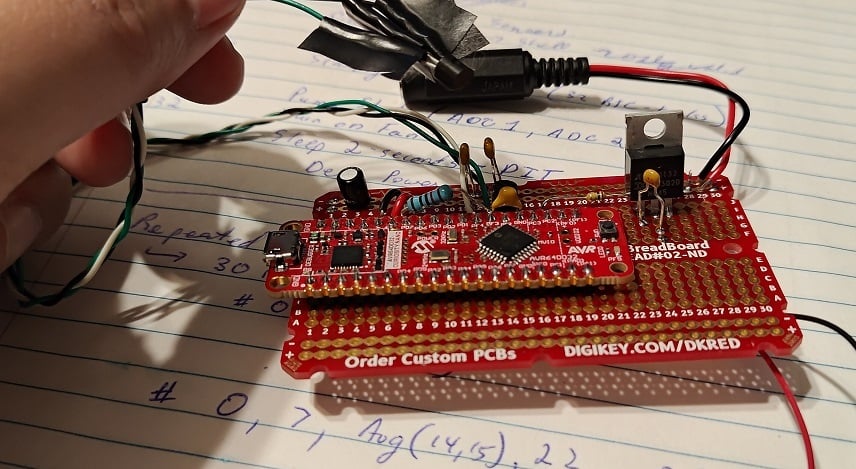 As usual, I'm using an AVR DD (this time: a curiosity nano devboard) for simplicity. (I expect to need the 32768 Hz clock crystal, so a PCB with said clock would be nice. Otherwise, the [DIP package is available](https://www.digikey.com/en/products/detail/microchip-technology/AVR64DD28-I-SP/16571745)). The overall circuit is pretty simple, but the topic of discussion today is the MCP970X series temperature sensor. https://www.microchip.com/en-us/product/mcp9701a At this point I do recommend people to read the documentation. The gist is that you simply apply 3.1V to 5.5V between Vdd and Gnd. Vout will have some amount of startup time, and eventually output 400mV + (Temperature-in-C * 19.5mV). For example, my room temperature is ~24C right now and the voltage output is ~920mV. (There's clearly errors in my ADC but I'm saving that for later... this device is _supposed_ to be outputting 876mV given the room's temperature) ------- With a ~6uA expected current, this device is power-efficient enough to run from most MCU pins. AVR DD's 50mA-per-pin is overkill, but more importantly, a through-hole design like mine seemingly has substantial inductance on all wires. The datasheets claim a startup time of 0.8ms. Alas, when I soldered on the MCP9701 and turned on the GPIO-pin, it took over 20ms (!!!) before the oscillating signal finally calmed down and settled upon the room temperature reading. To counteract this parasitic inductance, I've added a 10kOhm resistor and a 10nF capacitor out of my through-hole kit. (E12 resistor kit and E6 capacitor kit). With 220us of startup time now on the GPIO pin and with only 500uA max current going to Vdd... there is no more "ringing" anymore and life is good! EDIT: I should probably note that my goal was to return to 0.8ms startup time, like the documents suggest. 10kOhm was chosen as 500uA (5V) to 250uA (after charging to 2.5V) is a magnitude more current than I need and is a decent starting point. 10nF was chosen to pair-up with this to give me startup time in the 100us range but not over 800us (I don't want to be "slowed down" by the charging capacitor, so I want the Vdd charge to be faster than 800us claimed startup time). It should be noted that a 5V over 1000us curve was claimed as a 800us startup in the MCP970x documents if you read all the graphs. ------ Moving forward, my last task is that of calibration. The on-board ADC of the AVR DD is apparently quite accurate, but the Vref of the microcontroller is +/-4% (!!). With a +/- 2% accuracy of the temperature sensor, there is some calibration I should do. The ADC errors + Vref errors are expected to just be linear. The temperature-sensor's error is quadratic however. In both cases, I don't want to overcomplicate things, so I'm planning on just adding a constant-offset to the mV reading to shift it to the correct spot. -------- All in all: pretty standard Analog-to-digital conversion issues here. But I figured it'd be a good discussion topic for beginners.
Modern AVR has a wide variety of Timers (TCA, TCB most commonly, but TCD, TCE, and TCF are uncommon and specific to particular AVR chips). This can make choosing a AVR DD vs AVR EA vs AVR EB vs AVR DA a difficult choice, especially if you're trying to use timers to their greatest extent possible. This blogpost covers a basic idea of what the different timers offer. ----------- The blogpost is short enough. I feel like what I can add is to highlight the difference between: * Timers -- A background count++, a comparator of count vs some pre-configured values, and then likely an output pin that changes based off of these configurations. Consider this an MCU output. Almost everything listed can be used as a timer. * Counters -- Counter functionality is an **MCU input**. Many protocols, such as Servos, PWM, pulse-train decoding requires a variety of pulse-frequency-modulation, pulse-counting, or wide variety of other kinds of common tasks. "TCB" may be called a "Timer", but its really more of a counter-focused device which can more easily measure frequencies (for pulse-frequency-modulation). TCA and a few others can do some basic counting tasks, but usually not as well as TCB. The other discussions in the blog are easy enough to understand IMO. This is all AVR specific, but some of the best material online are highly specialized articles like this, so I still feel like sharing.
1.5 c Microcontroller alert. Very low-end, but 38kHz support is explicitly called out in its product manual. This means that this tiny uC is ideal for TV remote control (or other IR-blasters). I wouldn't recommend anyone use this chip unless you were some kind of professional saving pennies. Typical $1 uCs are far easier to work with and have exponentially more power (even $1 8-bit uCs). Still, its an interesting thought experiment for what a 1.5 cent uC could be used to implement....
 popovicu.com
This blogger booted an F1C100s from scratch, even though they made a mistake buying 16MBit instead of 16MByte of Flash. (Requiring to be booted off of USB-bootloader / Allwinner's FEL Protocol instead of Flash). So a few mistakes were made, but its still a custom booting Linux + blogpost that explains the steps.
 github.com
What really interests me about this design is the ~~buck~~ Boost-converter 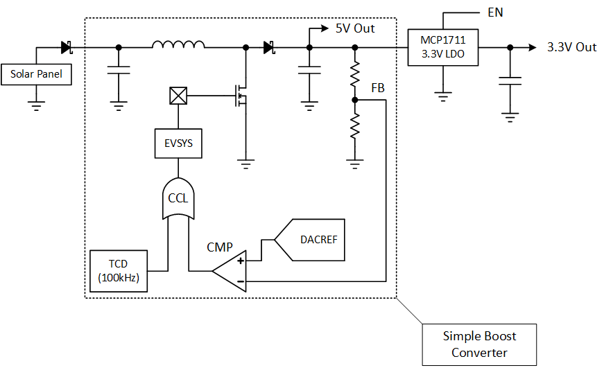 So this ~~buck~~ boost-converter is 100% core-independent. The Analog Comparator, TimerD, CCL, and Event-System are all active while the AVR DB **sleeps**, meaning that the microcontroller can run this simple ~~buck~~ boost-converter **without any cost to CPU time**. An incredible design that demonstrates the flexibility of AVR DB's combined peripherals.
 popovicu.com
Hacker News discussion here: https://news.ycombinator.com/item?id=40560300
 www.embeddedrelated.com
A random article talking about I2C on the NuttX RTOS. I haven't heard of NuttX before, but the supported platforms (https://nuttx.apache.org/docs/latest/platforms/index.html) is quite impressive, including several chips I'm interested in. There's a number of 8-bit processors (albeit larger ones) on the list, though I'd assume this NuttX OS is best served on a microprocessor??
 codedbearder.com
Edited the "I" for less confusion. The blogpost's title is "I made a...", but "I" (Dragontamer) didn't do this. I just found this blogpost and though it was relevant for this sublemmy.

I don't care what's it gonna take. I just want a connection. I guess I can connect the VCC to another voltage source, but I have the same thing happened to TX on another circuit board, although that one can "flip" (it is still attached marginally... at one end). Board: T Deck Lilygo.
 lcamtuf.substack.com

Some poor sap made a few hundred DIP chip labels for breadboarding that are designed for a little more functionality than is typical. They were uploaded to github along with a GIMP file, templates, instructions, and ready to print PDF files for labels and popular kits/projects like Ben Eater's breadboard computer and 6502 projects. The labels are intended to be more intuitive and informative than just pin labels, and these were made with brute force without programmic efficiency. For instance, many logic chips have truth tables and more. These take a lot of confusion out of the back and forth of documentation and wiring. https://github.com/Upcycle-Electronics/ChipLabels
This PDF talks about blue and infrared LEDs + photodiode and how to create a smoke detector out of them. The gist is to send a signal over blue LED + infrared LED, and then measure from the photodiode to see how much the light reflects back (which will only reflect back in the presence of smoke). This design uses the 2x free OpAmps on the MSPM0L (Cortex M0+) microcontroller, showing a mixed-signal design where one mixed-signal microcontroller can reduce the number of parts.
 www.viksnewsletter.com
Pretty basic but I've been enjoying Vik's articles on RF topics.
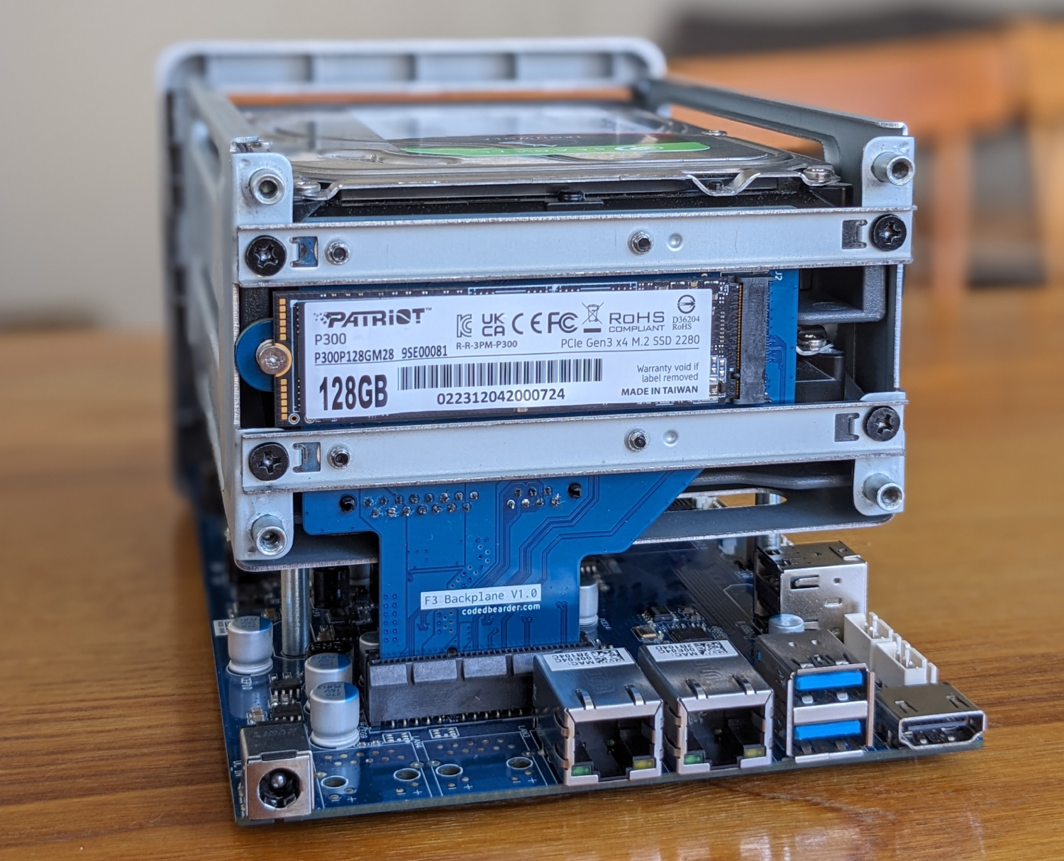
Hello everyone, I need some advice. I am making custom PCBs for a project of mine. It's basically for a little remotely controlled robot using little DC motors. I chose the Seeed Studio XIAO ESP32C3 as the uC since it has inbuilt wifi/bt, 3.3V regulator that I can use to power the motors (can source up to 700mA) and lipo charging management (the robots will run on battery). As you can see from [here](https://www.seeedstudio.com/Seeed-XIAO-ESP32C3-p-5431.html), the microcontroller is surface mounted and the pads for the battery are on the bottom layer. Same story goes for the thermal pad of the microcontroller and the thermal pad of the motor driver ([datasheet](https://www.tme.eu/Document/9504b4c07574a91a7b207d08475bca04/A3901.pdf)). I have worked with SMD components in the past and can solder them by hand, but I have never worked with SMD components that have thermal pads on the bottom layer. My question is: how to manage (route?) them? My PCB is 2-layer and I was planning on having both layers filled with a ground plane. Do I just connect thermal pads to the ground plane and call it a day? Wouldn't that make the components hard to solder with hot air? Do I make an isolated polygon that only acts as a thermal pad? Speaking of soldering is even hot air the way to go in this case? My PCB has components on both sides, and I was planning on ordering stencils together with the boards and using solder paste, placing the components and then using hot air to solder the components in place. I thought a hot plate would be better but I don't have access to one and I don't know how that works with components on both sides. I attached some photos of the PCB in Kicad, and [here's](https://github.com/EmaMaker/AMazeIng-robots) the git repo. If it is of any help, I'm planning of having them manifactured by JLCPCB. It is also my first time using KiCad, so go easy on me :) Thanks! [![][1]][1] [![][2]][2] [![][3]][3] [1]: https://files.catbox.moe/ztw2pb.png [2]: https://files.catbox.moe/hytn9j.png [3]: https://files.catbox.moe/l9nqcb.png
I found a radio from 2003 that was missing a power cord, and I first thought it needed a polarized C7 power cord, but it won't fit at all. Looking at it more closely, it looks like a polarized C2 connector, but it's also locking? I tried searching online but I couldn't find anything for the C1/C2 connectors that's polarized, not even considering the locking aspect. Is this something anyone is familiar with? It's not a high end or particularly old radio or anything. [Here is a link to a picture, I wasn't able to upload it to lemmy directly. ](https://ibb.co/fpLm5Fw)

I own a Samsung monitor, and when it's in standby mode the LED blinks all night. My hearing is so sensitive, and my room so quiet, that I can actually hear the LED powering on and off. So, every night I power it off manually. Sometimes I forget as I turn my PC off, and as I'm laying comfortably in bed, falling asleep, I hear it cycling, so I have to get out of bed, walk over, and turn it off, which delays my sleep. At this point I'm tempted to take off the bottom panel and break the LED with a screwdriver, but I'm worried that this might change how the current flows through the monitor's circuit board. I would appreciate any advice, suggestions or insights, thanks in advance!
 www.viksnewsletter.com
For those EEs interested in Wireless Communications like myself. Coming from more cellular communications type of stuff, I find the fact that 4096 QAM is possible over the air crazy.

This is from a module I'm using and I don't understand this part of it. https://files.waveshare.com/upload/3/3c/RP2040-Touch-LCD-1.28.pdf
 dmitry.gr
This post demonstrates a microcontroller bit-banging an old version of Bluetooth LE
MIT has a tradition of putting classes online for sharing. There's lots of good links here, so it should be a good reference for yall.
 chaos.social
This Mastodon post hit #1 on Hacker News today, I think people around here would be interested. Then you look at the $350 price point and walk away. 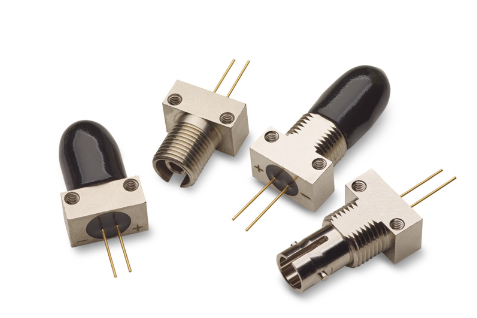
Atmel / Microchip created this Application note on how to drive the low-power and low-cost LCD segment displays. However, LCDs should be energized with AC signals, due to their internal capacitor-like structure. No worries: microcontrollers can send AC signals thanks to PWM-like on-off sequences. But thinking about this AC signal and how it energizes LCD segments is rather complex if you've never done it before. In fact, the electrical hookup here can be more complex than you expect. Its still a cheap hookup only requiring resistors directly connected to the pins, but... you need to think about this.  Note: If you're only doing a simple "Static" LCD, a simpler application note (https://ww1.microchip.com/downloads/en/Appnotes/doc2569.pdf) will be sufficient. But some LCD screens, especially the ones with more segments, will have multiplexing. And multiplexing requires a more complex signal and electrical hookup to accomplish successfully.
 floppy.cafe
Seems like a curiosity that people would like here.
 www.youtube.com
Wurth is one of the biggest capacitor companies in the world, and they gave this webinar about 7 months ago. I haven't watched it yet, but skipping through it looks pretty high quality. Alas, at 50-minutes, its a lot of information. So I'll have to watch this a bit later. But for a lot of beginners and intermediates out there, yall might not realize just how complex capacitors actually are. There's the dielectric material (aka: chemistry), there's size, there's various ratings, and more. Its difficult to find comprehensive rundowns like this video. Beginners/intermediates should definitely seek out this kind of information, to make sure you're buying the correct capacitors for your particular tasks.
cross-posted from: https://lemmy.world/post/9234776 > * Beginner Series I: What is a Microcontroller https://lemux.minnix.dev/post/10943 > * Beginner Series II: The "Generic" Microcontroller https://lemux.minnix.dev/post/23245 > * Beginner Sidenote: Microchip's Signal Chain Design Guide https://lemux.minnix.dev/post/64811 > * Beginner Series III: Skills and Complexity Tiers https://lemux.minnix.dev/post/81220 > > I think I've covered the material needed for a beginner to analyze and choose microcontrollers. However, a beginner may not be comfortable with reading datasheets, or families of datasheets. As such, I'll help beginners through microcontroller families. > > This skill where you can download a few spec-sheets, analyze them, and understand them is an absolutely necessary skill. There's hundreds of chips released every year from many manufacturers. And while practice with a specific chip is the only way to true expertise, there's still the "breadth" of knowledge that comes in handy when selecting chips. > > In this guide, I'm going to deep dive into AVR EA, the newest 8-bit AVR microcontroller from Microchip. But with commentary to help beginners understand the "big picture", how to evaluate this line and compare/contrast with other lines of chips. > > Why so many chips? > -------------- > >  > > Beginners might be flabbergasted to learn that there are 1498 available AVR-chips for sale, despite only ever being made by Atmel/Microchip. Of these, 1298 chips are the 8-bit AVR with mostly the same assembly language since the early 00s. > > AVR itself refers to the instruction set (https://ww1.microchip.com/downloads/en/devicedoc/atmel-0856-avr-instruction-set-manual.pdf), the assembly language / machine code that makes up all of these chips. Development tools (compilers, linkers, IDEs) are built on top of this ISA and therefore cannot change very much in practice. > > But many other features and specifications: the number of timers, 8-bit ADC vs 12-bit ADCs, DACs, UARTs, SPI, etc. etc. can and do shift on a regular basis. And ultimately, that's what leads to this chip proliferation. Its almost always possible to find a chip that does _exactly_ what you want it to do, at the lowest price, at the lowest power-usage. So there's a lot of marketing and swapping of features to create a perfect chip for every application. > > Microchip's AVR EA Family: (2nd) Newest 2023 era chip family > ----------------- > > So lets get started at looking at the AVR EA. (Oh no, while I was writing the AVR EB was released and I'm too lazy to switch now... oh well...). > > The webpage is a great starting point (https://www.microchip.com/en-us/products/microcontrollers-and-microprocessors/8-bit-mcus/avr-mcus/avr-ea ), but this only introduces the AVR EA family in general. We still have ... well... > >  > > All the other chips within the family. Now the main thing here is 28pin, 32-pin, and 48-pin pinouts... as well as 16kB, 32kB, and 64kB of Flash. Fortunately, the AVR Instruction set, and all the hardware (ex: Timer specifications, RTC, GPIO configurations, etc. etc.) are shared with recent chips (AVR EA shares very similar drivers with the AVR DD, AVR DA, and AVR DB chips released in the last 3 years). > > The homepage contains the following line: > > > The AVR EA family of MCUs is a great option for closed-loop control system designs and secondary monitoring devices for safety reasons. > > I agree with Microchip here, but how and why is this the case? What features from AVR EA make it ideal for this? Well, all in due time. > > Curiosity Nano / Development Boards > -------------------- > > All manufacturers create a "Development Environment" to help speed up experimentation with new chips. AVR EA is no exception, with the ~$25-ish AVR EA Curiosity Nano. > > https://www.microchip.com/en-us/development-tool/ev66e56a > > There is a USB programmer on board that works with MPLab and the legacy Atmel Studio IDEs, so you can easily develop from scratch (even without buying a special purpose programmer like Atmel ICE or building an AVRDude). > > 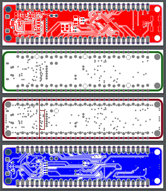 > > Microchip also releases schematics and PCB designs for these development boards. We can see that the AVR EA Curiosity Nano is a 4-layer board for example. All the relevant docs are in that area. > > Chip Programmer > ------------------ > If you leave the prototyping stage and start making custom PCBs, you'll likely find a programmer useful for your later-stage prototypes on your custom boards. > > https://www.microchip.com/en-us/development-tool/PG164100 > >  > > MPLab Snap is the $35 lower-cost programmer from Microchip. I've never used this tool, I'm using a legacy "Atmel-ICE" (which used to be the $35 range, but it looks like MPLab Snap is replacing it). For Atmel-ICE, I've never had a problem just connecting over USB, running the wires to my board header and sending the code through. I'd expect MPLab Snap to be similarly easy. > > Programming and Software > --------------------- > > Atmel Studio (now Microchip Studio) is my preferred IDE, but it is considered legacy. Microchip Studio still is a free download and still work with AVR EA chips today (just tested with my Version4 of my Battery-tester project). > > https://www.microchip.com/en-us/tools-resources/develop/microchip-studio > > I've only ever used the free and open-source GCC compiler for AVR. > > Microchip has been pushing hard for https://www.microchip.com/en-us/tools-resources/develop/mplab-x-ide , and I'd expect it to replace Microchip-Studio any day now. I do prefer the Visual-Studio based IDE though, but its hard to complain about free tools that work. > > Microchip also sells their XC8 compiler, and there's other compilers like Keil or IAR. But professional compilers are $1000+, and likely outside the range of hobbyists / beginners who are just getting started. In either case, the $0 GCC compiler and toolchain exists and works with both the $0 Microchip Studio IDE and $0 MPLab X IDE. There is a free version of XC8 as well that is missing a few features, but should be usable-enough for beginners. > > All of these tools provide the C-programming language (and maybe even C++ programming language), as well as linkers (combining .o object files together), the ability to create libraries, and a few libraries to help handle basic problems (Printf, atoi, etc. etc.). > > Some people prefer Arduino software, I don't know much about it and have always preferred the low-level C stuff personally. > > Can we talk about AVR EA yet? > ------------------- > > Oh wow, yeah, I guess that's a lot of cruft beginners need to know before they get to the chip. Lets start talking about the chip now! > >  > > Digikey has thousands in stock across 66 SKUs. Larger quantities can be ordered directly from Microchip in 5000+ at-a-time quantities (though it can take some weeks for larger quantities to arrive). Both Digikey and Microchip offer the Curiosity Nano development board that I talked about earlier, and that might be a better place to get started than the raw chips. > > But anyone thinking ahead to the custom-PCB phase of your project should see the SOIC, SSOP, TQFP, and VQFN packages of various sizes are all available. With some at extended temperature ranges as well. > > https://www.microchip.com/en-us/product/avr64ea32 > > The AVR64EA32 in TQFP was what I used for a most recent project. The 64kB Flash and 32-pin layout shares much in common with AVR DA, DB, DD, and older chips (very similar layout, size, pinout, and pcb-footprint), so I prefer using that over-and-over again in different projects of mine. > > HTML Version: https://onlinedocs.microchip.com/oxy/GUID-838DDB25-4D69-4519-815B-A48DBACEED23-en-US-9/index.html > > PDF Version: https://ww1.microchip.com/downloads/aemDocuments/documents/MCU08/ProductDocuments/DataSheets/AVR64EA-28-32-48-DataSheet-DS40002443.pdf > > Entering the manual, we have 565 pages of documentation. This is pretty small for modern chips, and this is due to the relative simplicity of 8-bit chips. (Many 32-bit chips are closer to 2000+ pages long). There's no need to read every single page of the manual, but instead immediately bring your focus to the following pages. > > The first pages are a 5ish page summary of all features. I'm not going through the entire list, but I want to draw attention to: > >  > > 12-Bit ADCs are available on a lot of chips these days. But **Differential** and **PGA** are eyebrow raising. These are relatively rare features that are incredibly useful in the application of current-sensing. This suggests to me that the AVR EA is for reading current and reacting to current-changes (such as the 4-20 mA current loop protocol). This is absolutely the "killer feature" of the chip, and is the reason to pick AVR EA if you have any current-sensing use in your application. > > Most chips have a "killer feature" like this somewhere. It could be very high memory (264kB on the RP2040), it could be incredibly accurate ADCs (RX23E-A), or whatever. Knowing and remembering that this AVR EA chip is extremely useful for this niche is something you'll have to keep in mind for all future projects, thinking of what the best chip for your project could be. > >  > > Next, you'll want to look at the port multiplexing. > >  > > Only **some** features are available on **some** pins. AVR chips are more flexible than most thanks to the Event-system (some outputs can go onto the event system and be routed arbitrarily), but outputs are often tied to just a limited number of pins. If you're making a PCB layout, you'll have to keep these pin-multiplex issues in mind. > >  > > From there, skip all the features and just read the Electrical Characteristics. Keep in mind your voltage-levels, the capabilities of pins, and any features of the hardware you're interested in. > > Don't forget Application Notes > --------------------- > > Going back to the AVR EA landing webpage leads to the documents section. Check it out. > > 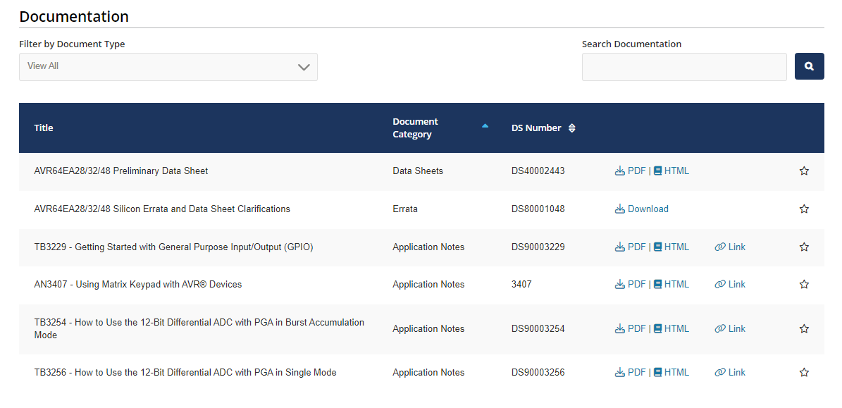 > > If you're not experienced enough to see the "killer feature" of a particular chip, look at the App Notes. They likely suggest situations that the chip is good at. They're trying to sell you this chip after all, but these App Notes (despite being marketing / sales purposes) are still good technical information that will teach beginners how to think about projects. > > In particular, https://ww1.microchip.com/downloads/aemDocuments/documents/MCU08/ApplicationNotes/ApplicationNotes/AN4811-CurrMeasurem-BattMon-DS00004811.pdf > > AN4811 is an AppNote covering how a 12-bit Differential ADC with 16x PGA (on the older ATtiny1627 chip, but still applicable to today's AVR EA) can be used as a battery monitoring / Coulomb counting application. > > Honestly, I'd say that these Application Notes are the #1 source of information for beginners and intermediate engineers who need some hand-holding to learn how to use these chips (or chip features). > > Thats it, I guess? > -------------------- > > Well, I don't want to hold up everyone with an even longer article. But I think I've covered the crux of how to read a real world Microcontroller datasheet. There's hundreds of other pages in the datasheet and not enough time to cover it all, but I think I was able to at least cover the basics. > > Would anyone be interested if I gave a rundown of my AVR EA Battery Tester project some time later?
Nevermind. I think I had a brainfart. Lol. Deleting topic.
I was reviewing a recent project of mine, comparing the LTSpice simulations vs my real physical circuit, when I noticed that there are effectively two independent ways of measuring "ESR". So lets slow down for beginners for a moment. When EEs teach resistors, capacitors, and inductors to students, we are basically lying to you. There's no "ideal capacitor". All capacitors exhibit parasitic elements (aka: acts a little bit like a resistor or inductor), and not like the ideal math from the beginner world would imply. But there's a 2nd layer to this, and it hits at the core of ESR/Impedance vs Dissipation Factor. Depending on how you test these parasitic elements, the value will change, sometimes dramatically. Lets look at the 330uF WCAP-ASLI capacitor I chose for my project more closely. https://www.we-online.com/components/products/datasheet/865080145010.pdf  DF is created with one test, while the "Impedance" value here is a separate test. (Note, there is a frequency-dependent component with these parasitics, but according to RedExpert, frequency doesn't affect us in this particular discussion). https://redexpert.we-online.com/we-redexpert/en/#/redexpert-embedded  Also note: the ESR in _this_ graph has been measured to be under 200mOhm (so yet a 3rd, completely different value to add to our mix!! Hurrah, I'm going to ignore this one, I've got enough trouble just talking about the other two "ESR" values already calculated in this topic...) So DF is **supposed** to be related to ESR with the formula: ESR = DF / (2 * Pi * Frequency * Capacitance), or ~0.95 Ohms in this case. But... ESR/Impedance has been measured to be 0.34 Ohms, a rather substantial difference. What gives? I'm going to admit that I'm now entering the realm of ignorance. I don't know why we have to different tests for what amounts to be an ESR test. But what I can say is that DF is measured at 120Hz, suggesting that the DF is more applicable to 60Hz power-line mains. While Impedance/ESR values are tested at higher-frequencies, suggesting a test more applicable to boost/buck converters or the like. Since the values / specifications of ESR differ so grossly depending on "how you test for it", it behooves the EE to not only read these specifications, but understand the tests **behind** the specifications. So that we can better predict what will happen in reality. I assume that anyone building a full-bridge rectifier at 60Hz power lines (or 120Hz after rectification) will want to use dissipation factor values instead. In particular: it seems like the Dissipation Factor (and the ESR-calculated-from-dissipation factor) is a strong estimate on the amount of Watts-of-heat generated from a 120Hz power-line (after full-bridge rectification). For some applications, its this heat generation that's the most important thing to calculate. But for my purposes, where the capacitor is basically a decoupling / energy storage capacitor, Dissipation Factor (and its associated ESR of 0.97 Ohms) is not a good estimate on the final ripple going into/out of my boost converter. In this case, the Impedance value above (ie: 0.34 Ohms) is a superior estimate to what's happening in _my_ circuit. And this is engineering. Understanding not only the specified values, but choosing which value to think about deeper depending on context. The EE-world is full of little contradictions like this.
 lcamtuf.substack.com
Lcamtuf conducts the classic "Hook up a signal generator to a coax-cable" to study some basic transmission line theory.

So I made an antenna based on a design on thingiverse/blog post. IIRC this is some Yagi variant. I did the math and did a bunch of tedious stuff to try and make it a proper project at the time. I do not have a network analyzer, smith charts are for shaman/wEEzards, and radio is the work of the devil. I was looking to extend the range of the 2.4G channel across my house just slightly using directionality. Empirically, it worked at first. I'm here half trying to diagnose, and half trying to understand some fundamental circuit design basics. The 2.4G output has two channels coming from the same peripheral radio chip. Normally these go to the dipole antennas. I used the same micro coax connector and proper coax throughout, with proper grounds/solder station/flux/etc. The continuity tests good still. The router automatically tries to move the transmit and receive signals between the two separate 2.4G channels under normal operation, but it drops one channel regularly now. I can see this on the network status of a connected device, and the drop happens regardless of proximity. I have not physically tested that the dropped channel is the one that had my DIY antenna. It could be a software problem. My curiosity is could this asymmetry cause a common failure mode, other than something obvious like ESD? I etch, design, KiCAD, toner transfer, photolithography, and Arduino my way around in this space as a hobbyist, but like, I'm too lazy to go on the eevblog forum to ask this formally and radio is magic IMO. This is the output stage in a bad hand held half ass pic with no attempt to do things like clean off the residue on the chips from the thermal pad that rests over them. 
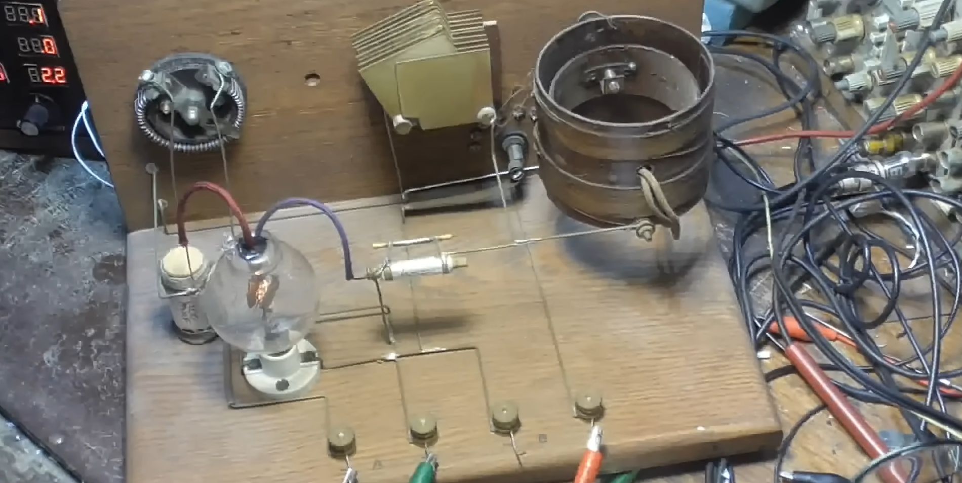
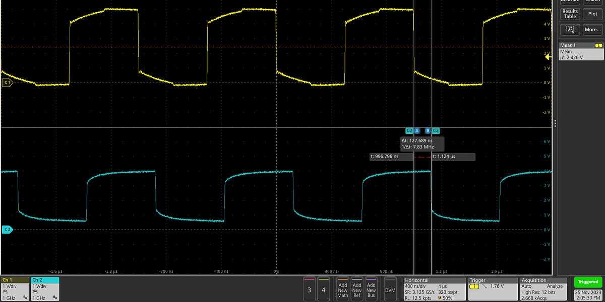
Preamble: I have been pushing the "I believe" button for way to long when it comes to crystal oscillators and their supporting components. The concept is simple, as they generally consist of proper loading and some kind of (pre)amplifier. "Small thing shake fast and you amplify". However, the full concept has never "clicked" in my brain and it feels like a huge knowledge gap that I should have filled years ago. Asking these questions is horrendously embarrassing since I am a licensed ham and I should intuitively understand how all resonant circuits work by this point in my life. (Hopefully, y'all have a better way for me to visualize resonant circuits in general.) ----- From this schematic, all I see is a DC source, an amplifier, and maybe a super-simple RC tank circuit (of sorts) and the wave should never drop below 0v: 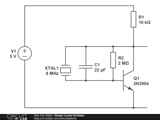 Some of the most basic crystal schematics (concept diagrams?) show a crystal connected directly to an AC source. The concept of a crystal is simple: Apply a voltage and it moves, remove that voltage and it returns to its original shape. That kind of explains why kick-starting oscillation is needed, but that is not really where I am confused. My questions are: Is the crystal more closely related to an inductor in a basic RLC circuit? Is L being an approximate relationship to X a good way to visualize this? Does the crystal "force" an RC resonant circuit to operate at a specific frequency because of its tendency to only operate efficiently at a given frequency in wildly different environments? (This question is a result of the first: Does an inductor act like a crystal in some ways?) Since basic BJT amplifiers are generally shown with super-basic crystal schematics, is that amplification a functional part of generating a wave form? So, if the BJT was removed, the circuit would still function but it would be at a much lower current? (TBH, I am getting a gut feeling that the BJT is functionally related to an opamp with feedback in the above schematic, maybe?) Thanks in advance for any education. Cheers! (Oh, I do understand we are mixing AC and DC circuit concepts here, so that isn't an issue for me either. I also could just "look at the formulas" for building crystal circuits, but I need a better understanding of the core concepts first.)
So I was thinking about Flash memory today, and I realized that the FTL / Flash Filesystems are overly-complicated for a lot of microcontroller applications. Still, microcontroller projects need some way to ensure that the NAND Flash wears out evenly (some uCs, like the AVR DD, only has 10,000 erase/write cycles on its Flash). ------------- The traditional answer is of course, FTL (Flash Translation Layers), a component of modern Flash-based filesystems. As a modern filesystem writes data, the FTL remembers how many times each Flash-page has been written to. The FTL / Page allocation logic ensures that the least-used page gets malloc()'d next, and therefore balances the erase cycles across all the flash to maximize endurance. In particular, when the application code wishes to "erase" a Flash page, it instead is "malloc()" from the pool of flash (usually: the one with the fewest erase cycles), while the old page is conceptually free()'d back into the pool. (a process known as "TRIM" on modern Flash controllers) This way, as the application-code writes files (or rewrites files), the FTL walks across the whole flash and load-balances the erase cycles. Things can get far more complex (ex: static wear leveling), but this is enough of a discussion that I think beginners can follow along now. -------------- Anyway, the FTL itself needs a wear-balanced data-structure. I can imagine a few off the top of my head (writing to a journal-like log of FTL pairing changes)... where the Microcontroller would read the whole log upon startup and "recreate" the most recent data (ensuring integrity even in a random power loss). After all, the FTL itself needs to be persistently stored, and the best place for that is... well... the Flash system you've got. So FTL persistent storage data-structures necessarily solve this problem. But I was wondering: is there a book, an encyclopedia, or other such reference which discusses wear-leveled data-structures **such as** the FTL? I have to imagine I'm not the first programmer to think about using these 64kB or 32kB Flash Microcontrollers in a wear-leveled manner. Someone out there must have implemented something and wrote about it! EDIT: For my research, I'm looking into JFFS2, YAFFS, and other Flash-based embedded filesystems to see if their source code has any references to anything, or other such concepts. But if anyone has pointers for me on this question I'd be very interested!
To get myself back into electronics, I pulled out an old project idea I've been wanting to do for a while, and that's a AA NiMH battery tester. I have a collection of ~30+ AA NiMHs that I use for various purposes: Flashlights, Switch Controller (yeah, they made an attachment), Electric Toothbrush, Walkie Talkies, etc. etc. After a few years of abuse, these AA NiMHs degenerate, but at different rates! Even though I bought them all at roughly the same time, different levels of abuse made _some_ cells barely hold a charge, while others work almost like new. How do I differentiate between them? Simple: charge up the AA cells, then perform a current sensor / coulomb count against them. That is: measure the current out x time taken == total amp-hours that a particular AA cell can take. And if this value drifts too far away, I recognize it as a busted cell and send it to my local Home Depot for recycling. First, I'll go over the schematic one-at-a-time for everyone. V3? What's version1 or version 2? ------------ Erm.... mistakes were made. Lets not talk about V1 or V2 right now... 7 Segment LED Driver ------------- 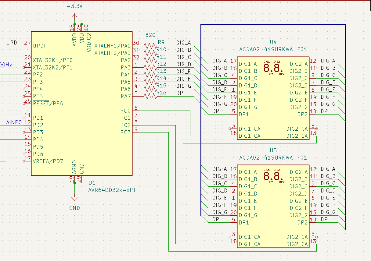 The "Digital" half is pretty simple, I take the surface-mount ACDA02-41SURKWA-F01 (https://www.digikey.com/en/products/detail/kingbright/ACDA02-41SURKWA-F01/3084667) 2-character 7-segment LED x2, and hook them up as appropriate to an AVR DD microcontroller. At 3.3V Vcc and 1.6V Vforward LEDs, a 820 Ohm resistor will let ~1.8 mA of current, which testing has shown to be plenty bright enough for my purposes. For the newer EEs out there, these devices are very dumb. https://www.kingbrightusa.com/images/catalog/SPEC/ACDA02-41SURKWA-F01.pdf   These "Common Anode" LEDs have high-voltage all running from the same wire. So they only work with a little bit of microcontroller magic: I turn on one-digit at a time (ex: Digit#1 goes to high-voltage, then I can display a 0 with the binary output "11000000" (low-voltage on segment abcdef, and high-voltage on segment g). I then turn Digit#1 off (set voltage to low), and then set Digit#2 to high, and display the same ports "10011111", which will display the "1" character. Etc. etc. I can cycle through Digit1, 2, 3 and 4 a thousand-times per second so that the human eye cannot see them changing so quickly. This ultimately displays a 4-digit number. Battery, Current Sense, and Instrumentation Amplifier --------------------  The battery is just that: a single AA-battery holder. The entirety of this circuit runs through the 0.1 Ohm current sense resistor, meaning even the power behind the microcontroller/LEDs gets "counted". For beginners out there: an OpAmp is an "analog computer", allowing electrical engineers to add, subtract, multiply, divide, differentiate, or integrate voltages. An Instrumentation OpAmp is a specialized OpAmp that focuses upon differential signals and multiplication with a constant (aka: C * (A - B) type calculations, where C is a constant). In particular, Instrumentation Amplifiers increase the accuracy of the (A - B) calculation by maximizing the CMRR (common mode rejection ratio), aka the "minimization of error from changing voltages", and PSRR (Power Supply rejection ratio), aka the "minimization of error from changing power-supply". As a tradeoff, Instrumentation OpAmps have worse bandwidth and less flexibility. A Zero-Drift Amplifer is a further specialization that focuses upon very low offset voltages (aka: the where the OpAmp thinks 0-voltage is located in reality). Nominally, you could use a general-purpose OpAmp, but its always best to pick the specialized amplifier for any particular job. As such: I picked the MCP6N16-10 is a Zero Drift AND Instrumentation amplifier. Because its zero-drift, it has 20uV specified offset voltage (or 0V will be somewhere around +/- 0.00002V in reality). There's a further requirement that the MCP6N16-10 only works if I set the gain (aka: the "C" in C * (A-B) calculation) at 10x or higher. In this case, I set the gain at 27.3. Now lets step through what happens here: When say 500mAmps rushes through the current-sense resistor  V = I * R Thus, the 500mA * 0.1 == 0.05V change across R1. MCP6N16-10 very accurately performs (R1_high - R1_low) calculation (thanks to very low offset voltage), and thanks to the 27.3x multiplier, will output 1.365V. I then added a 100k / 10uF simple low-pass filter for anti-aliasing as well as averaging out in the analog domain. This effectively creates a moving average of the most recent ~6.28 seconds. (Or perhaps, I have a low pass filter with Fc of 0.16Hz if you want to think about it in the frequency domain). After all that, it goes into my Microcontroller. I've configured the AVR DD to have a 2.048Vref for the ADC. Alternatively, you can think of the 27.3x multiplier + 0.1 Ohm resistor + 2.048V Vref and 12-bit ADC to reasonably accurately measure resolutions of ~180 microamps per least-significant bit, across ~0mA through 750mA or so worth of nominal range. All resistors are +/- 1%, though the Vref of the microcontroller is +/-4%. The load ----------------  A very simple low-side NMOS switch driven by the AVR DD. More on this later, I think I made an error with this version that I'm fixing in my next design. But the uC simply drives the NMOS high to let the 2.2Ohm resistor send ~500+ mA across the battery. The 3.3V Boost Converter ---------------  Various parts on this board require more voltage. The whole board is powered by only a single AA cell, which will vary between 0.9V to 1.4V depending on how charged the AA cell is. The boost converter takes this voltage / current / power, and converts it into 3.3V. The design here is simply following the MCP1640BCH data-sheet, and then picking new resistors that were found elsewhere on my board (instead of the original resistors that were in the docs). KiCAD Notes -------------- KiCAD is a free CAD tool to help create PCBs. 1. Create and/or Select Symbols -- These represent the various chips and parts you'll put into your design. 2. Create a Schematic -- KiCAD will use the schematic to automatically check which parts need to be connected to each other. 3. Create and/or Select Footprints -- Each symbol is then given a footprint, the 2D representation of how it will look like on a PCB. 4. Layout PCB -- First configure the PCB to have the settings of your manufacturer. click "Update from Schematic" to import data from step #2 and #3, and then just arrange the items in the PCB editor till things look good.  The PCB Manufacturer ------------- I wanted to try out DKRed this time. https://www.digikey.com/en/resources/dkred I chose the 2-layer PCB settings and configured KiCAD with the board specifications. 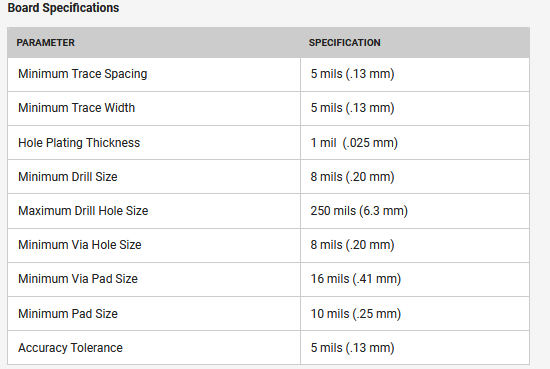 The PCB Design ------------  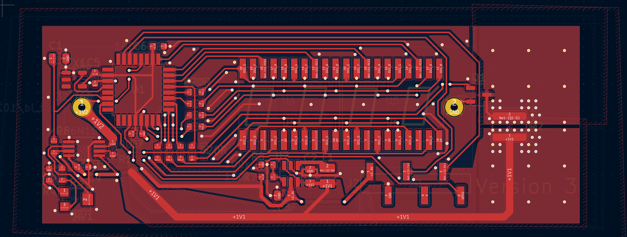 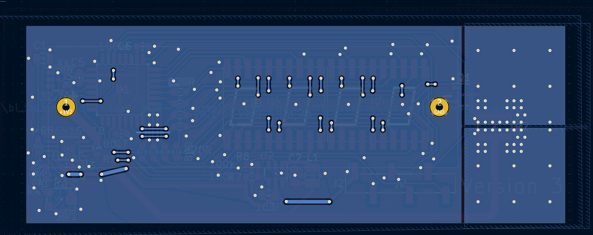 It is impossible to have a solid ground-plane on a 2-layer board, but I made the ground plane as solid as I possibly could. Of note is the PCB-heatsink on the right side of the board, as well as the "sideways resistor". Let me bring attention to the 2.2 Ohm resistor really quick. https://www.digikey.com/en/products/detail/vishay-dale/RCL12182R20JNEK/2556524 This resistor is designed with "sideways" leads so that the heat would more easily transfer into a "PCB Heatsink". All a PCB Heatsink is is a large section of copper you leave for non-electrical reasons... but just for the heat-sinking reasons alone. The Mistake: Bad EMI??? -------------- Did you catch the mistake? In my haste to maximize the PCB Heatsink size, I've removed the ground-plane from under the 2.2 Ohm resistor. Now... maybe in isolation that's not a big deal. Except upon finding and testing this design, I've found that the rise-time of that NMOS is 20 nanoseconds in practice. And when the voltage reaches near the 0.95V cutoff mark, the code will purposefully PWM to try to train the last bits of the AA cell down to the 0.95V cutoff. (When a cell is 0.94V, it cuts off the NMOS, but this immediately causes the voltage to increase back to about 1.02V, causing the code to turn the NMOS back on... causing the voltage to drop to 0.94V, etc. etc. at a rapid rate). I'm fairly certain that I've got bad EMI noise in the 50MHz+ range in practice, though I don't really have a means to test it. My next version will be a 4-layer board with better respect for grounding issues. As it turns out, a significant amount of the traces going to the 7-seg LEDs use a good amount of room (and also cut up the ground plane on the 2nd layer). So I think a 4-layer board will shave off a few more millimeters off the width of this design. My next version includes a "slow start" capacitor on the NMOS, to have microseconds of risetime on the NMOS rather than the 20ns of risetime in this prototype. Also, with a 4 layer board, I should (theoretically) minimize any EMI issue that would come about (not that I really have a good measurement tool for that). Prototyping and Assembly --------------  I applied low-melt lead-free solder paste, manually placed all the parts with a tweezer. For those who have never used solder-paste, its pretty easy. Solder paste is sticky enough that the parts remain in the proper place after you stick them on. I did buy a solder paste stencil (~$10 these days) to make the application of solder paste braindead easy on my 3x prototypes. I used the "Electric Skillet" method (turn on the skillet until the solder paste melts, turn off the skillet, then use hot-air rework station to fix any tombstones). Thanks to the magic of solder and surface tension, the solder itself will mostly pull themselves into the correct spots when the solder is molten. So you don't need to be very precise with your placement. I used a x10 Loupe to inspect for solder bridges. Solder bridges were fixed with a soldering iron + solder wick. Once the surface-mount parts were all confirmed to be good, I added the AA-holder to the back and used traditional leaded-solder to attach the pin through the though-hole... erm... holes. 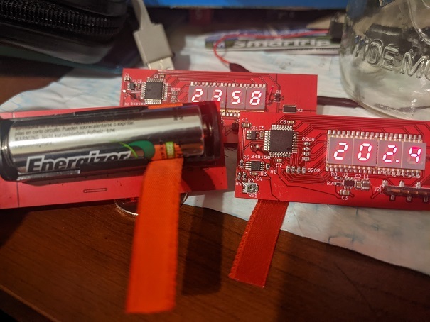 I'm fairly certain that I messed up the fragile oscillators due to neglect. My clocks are **severely** off, by 5% or so (the clock is supposed to be 20ppm, or 0.002% accurate, so 5% is severely off). So next time, I'll be more careful about my soldering procedure. Programming -------------------- Microchip Studio is pretty straightforward, and I don't think the code is very difficult. I manually initialized the various hardware bits of the AVR DD by reading the manual.  Initialization routines have a recipe from the manual to follow and the documentation is rather straightforward. I did come across a bug with "AC_MUXNEG_DACREF_gc" being the wrong value (shame Microchip!! You messed up your .h files!!), but it wasn't too difficult to see the error when the code ran and I fixed it up in a few minutes. (manually used the value from the manual: 4). Code is written in polling style, there's no OS here so I just have an infinite loop that's checking for the clock to change and reacting to the clock. 4096x per second, I update which digit I'm displaying. 1024x per second, I cycle through all 4 digits. I use 16-bit BCD so that I only need to bitshift + AND to extract the values in this most common operation. 64x per second I check the Analog Comparator for if the battery has dropped below 0.95V. If so, I turn off PortF (the NMOS). 16x per second I update the milliamp BCD number to display later. I have a very expensive division / modulus operation here, but the AVR DD even at 4MHz is fast enough to perform this operation without causing issues in practice. I also have a moving-average queue to average out the last 16 values (ie: 1 second), to help cut down on noise in the display. 2x per second I update the AmpHr number. AmpHr is a 64-bit fixed-point (32-bit above 1.0, and 32-bits for the fractional half). 1x per second I swap between AmpHr display and miliamp display. The ADC updates as quickly as possible asynchronously. There are no interrupts, I simply read from the ADC regularly and add the ADC value to the 1/64th miliamp variables (which will be divided out / normalized later). The code is only 250 lines long with substantial amounts of comments. I don't use interrupts, I simply poll with if() statements on all the above conditions. Everything completes fast enough ("realtime enough") that all the code just works without any of the complex features available to me. Calibration -------------------- I pulled out my benchtop Fluke 45 to calibrate the ADC errors with a #define. This is an old benchtop multimeter with ~5 digits of display, giving me accuracy to 0.0001Amps of measurement. (Alas: the more accurate measurement of 100.00 mAmps only works at 100mA and less, and my design is 500mA). I've noticed a decent amount of non-linearity. I wonder if I'm leaking current somewhere? Or maybe there's more offset error due to something unknown? Still, the overall error is within 1% across the range, and maybe I could calibrate both a zero and the 500mA points to help minimize this non-linearity. Calibration is just me changing a #define in the C code. Nominally I have a 2k trimmer pot here, but it seems like #defines to trim away the error was sufficient in practice. Next version won't have the trimmer pot. Questions? ---------------- Lemme know if anything doesn't make sense to yall. I don't think this is an especially difficult project. I hope I gave enough details so that the newer EEs in this community could follow along. Feel free to ping me for questions. I know someone out there was looking for a current-sensor project. This is my current sensor project, probably different than what you are going to build, but maybe its a source of inspiration for you.